The two valves in the flow to the cylinder and radiators in this diagram would be the motorised valves controlled by the cylinder and room thermostats. Part in the heating wiring series covers how the port mid position valve works internally, allowing separate positions from only mains inputs. What type of wiring is used for central heating?
What is a central heating diagram? Electrical wiring for central heating systems. Part in the series looks at Y plan wiring, a system which uses a single port valve.
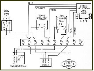
This has one inlet and. The valve itself has three plumbing connections - in, out A and out B. Regardless of other settings, at least one of the outlets is always open, so it is always possible for water to flow through the valve. Outlet A is normally connected to the central heating, with B used for hot water.
The usual arrangement in this case uses a 3-port "mid-position" Motorised Valve to direct the pumped flow from the boiler to either the central heating circuit or the hot water cylinder, or both simultaneously. Internal workings of the valve.
Diagrams are available for all Warmup Thermostats whether you are installing it as part of a hydronic underfloor heating system, a simple combination boiler configuration or even a multi-zoned. In the central heating and hot water "both off" state, the system wiringin grey being live.
A motorised valve is used to control the flow of water in a central heating system.

Pipe size Way 22mm bar. The motorised valve can be. The OP could use one zone valve and one mid-poss valve, with the controls I advise but remember a mid-poss valve has limitations regarding the heat carrying capacity.
Showing flow from boiler, to Y Plan, or Mid Position Diverter Valve, and then onto heating or hot water circuit. WORK MUST BE COMPLETED BY QUALIFIED ELECTRICIANS OR HEATING ENGINEERS. Combination Boiler with Heating Zones, Relay Switching Heat only and system boilers Y Plan central heating system Y Plan Heating with Unvented Cylinder and Port Valve S Plan central heating system W Plan central heating system Central Heating Programmers Room thermostats for heating systems Hot water cylinder thermostats Frost Thermostat.
The white and grey wires are the control inputs, the orange is the output to the boiler for port A open, and blue is neutral. Wiring Confusing Of RwbTimer Diynot Forums. If the programmer or time clock have no ‘Hot water OFF’ terminal then the time.
It shows the components of the circuit as simplified shapes, and the aptitude and signal contacts in the midst of the devices. HSA3D Diverter Actuators.
Thread Status: I would fit a Honeywell and require back to the main wiring center. Megavolt, Jan danfoss hsawiring diagram. Here is a picture gallery about honeywell port valve wiring diagram complete with the description of the image, please find the image you need.
The Drayton LWCwiring centre has been introduced to meet this requirement. The LWCis suited to all popular central heating and hot water systems, with adequate wiring space.
INSTALLATION Before fitting the valve, read through the plumbing and wiring instructions. For list of programmers to attach to this circuit - see page 19.

Before I wired in the new valve I was getting heating on with water aswell. The programmer seems now to be working the other way round. Collection of zone heating system wiring diagram.
Click on the image to enlarge, and then save it to your computer by right clicking on the image. Assortment of central heating thermostat wiring diagram.
A wiring diagram is a streamlined standard photographic depiction of an electric circuit. It reveals the elements of the circuit as simplified shapes, as well as the power as well as signal links between the tools.


No comments:
Post a Comment
Note: only a member of this blog may post a comment.